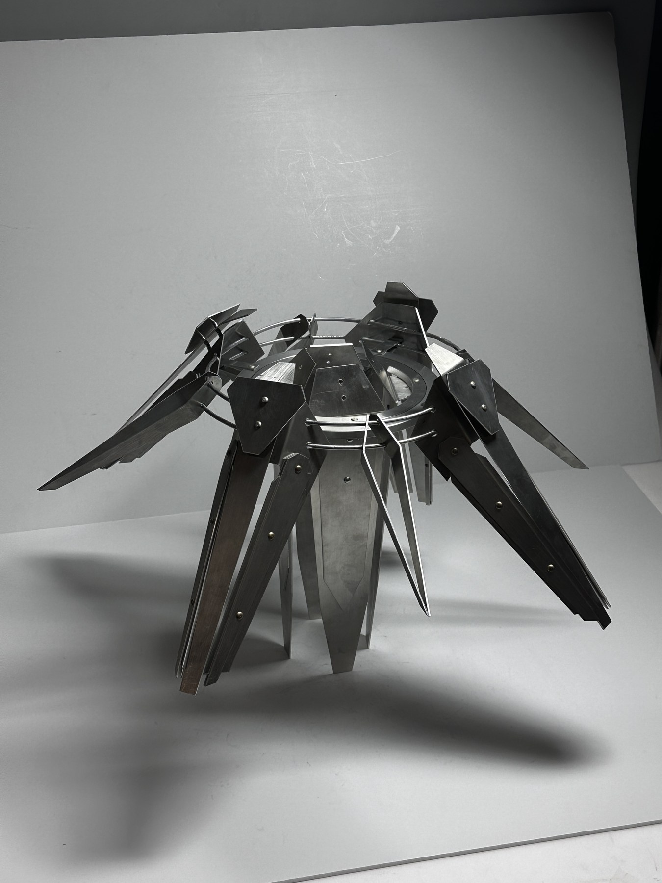
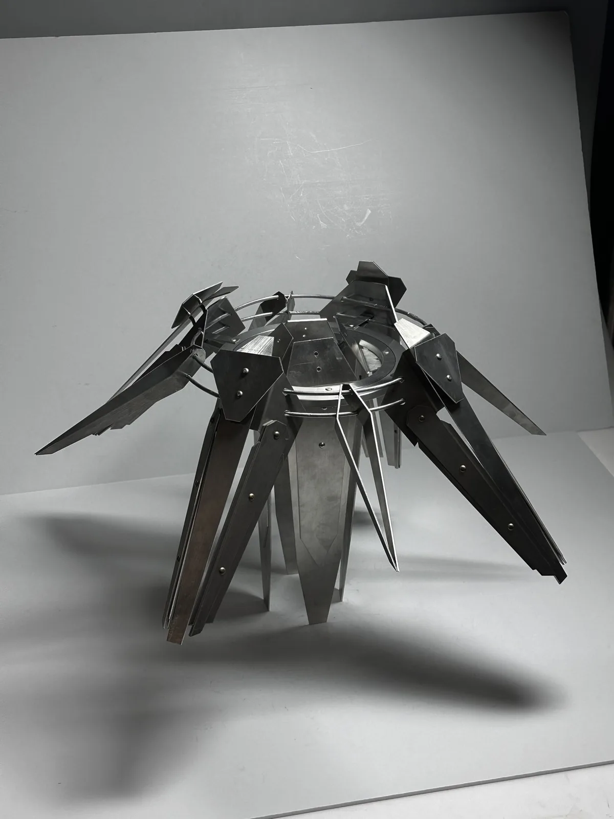
How can an aggressive, beam-like form remain legible after every surface becomes a cut and joined piece of aluminum?
The project began in Rhino with a radial silhouette inspired by science-fiction energy devices. Technical planning then translated that form into repeatable planes, concentric rings, bent rods, and visible fasteners that could be fabricated and assembled by hand.
COURSEID METALS I
FOCUSFORM · FABRICATION
TOOLSRHINO · TECH DRAWING
OUTPUTPHYSICAL PROTOTYPE
SEC 02
Radial Assembly放射结构
REPETITION CREATES THE SILHOUETTE
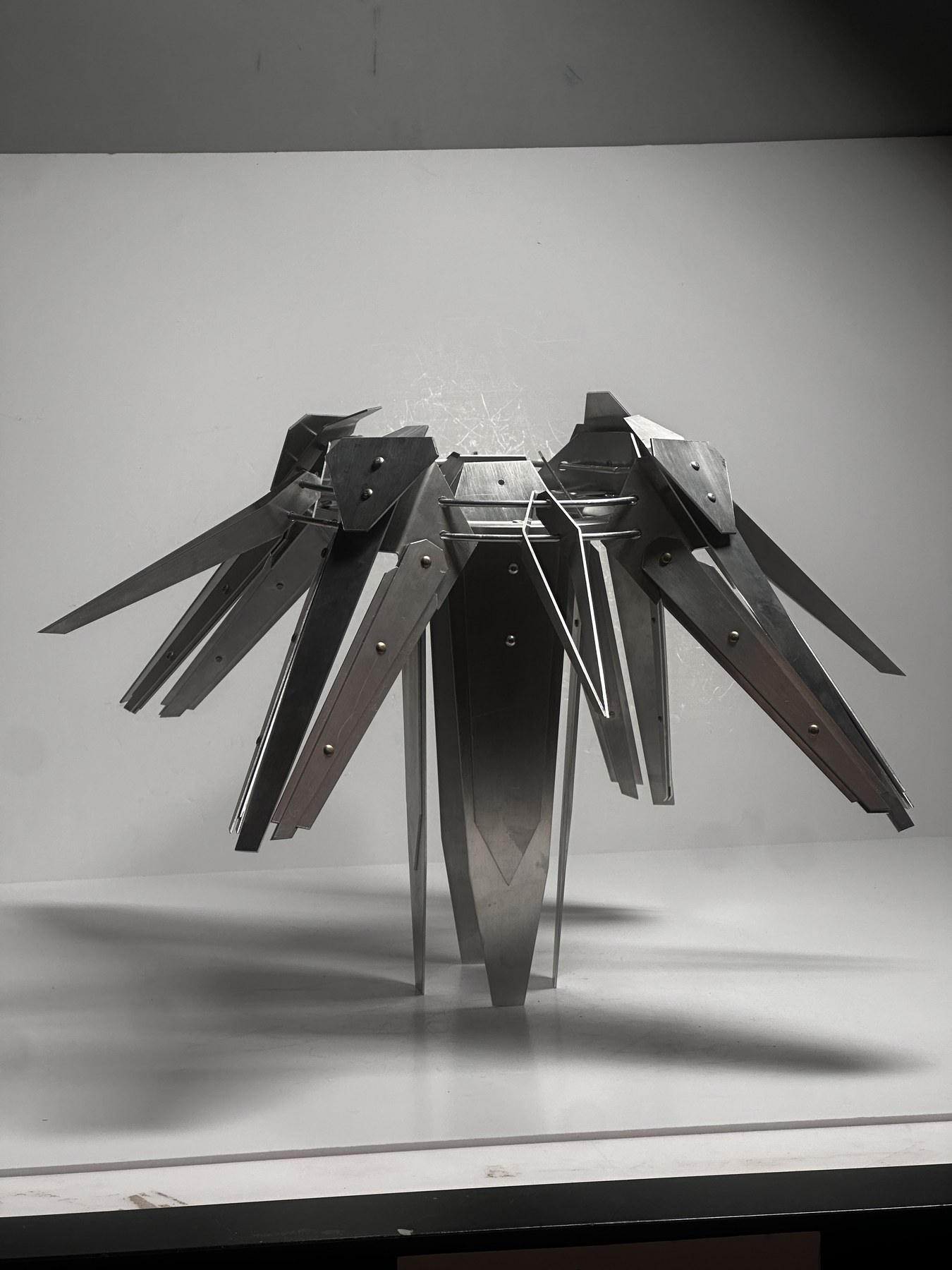
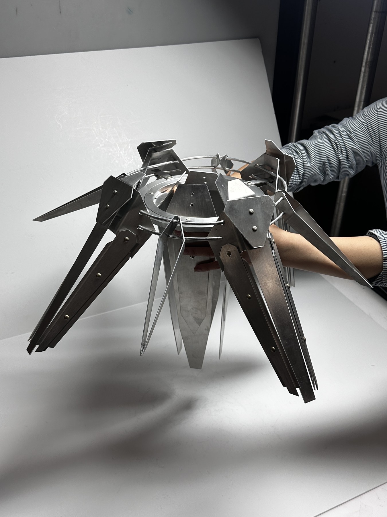
Layered fins orbit a central ring, turning a collection of flat parts into one directional volume.
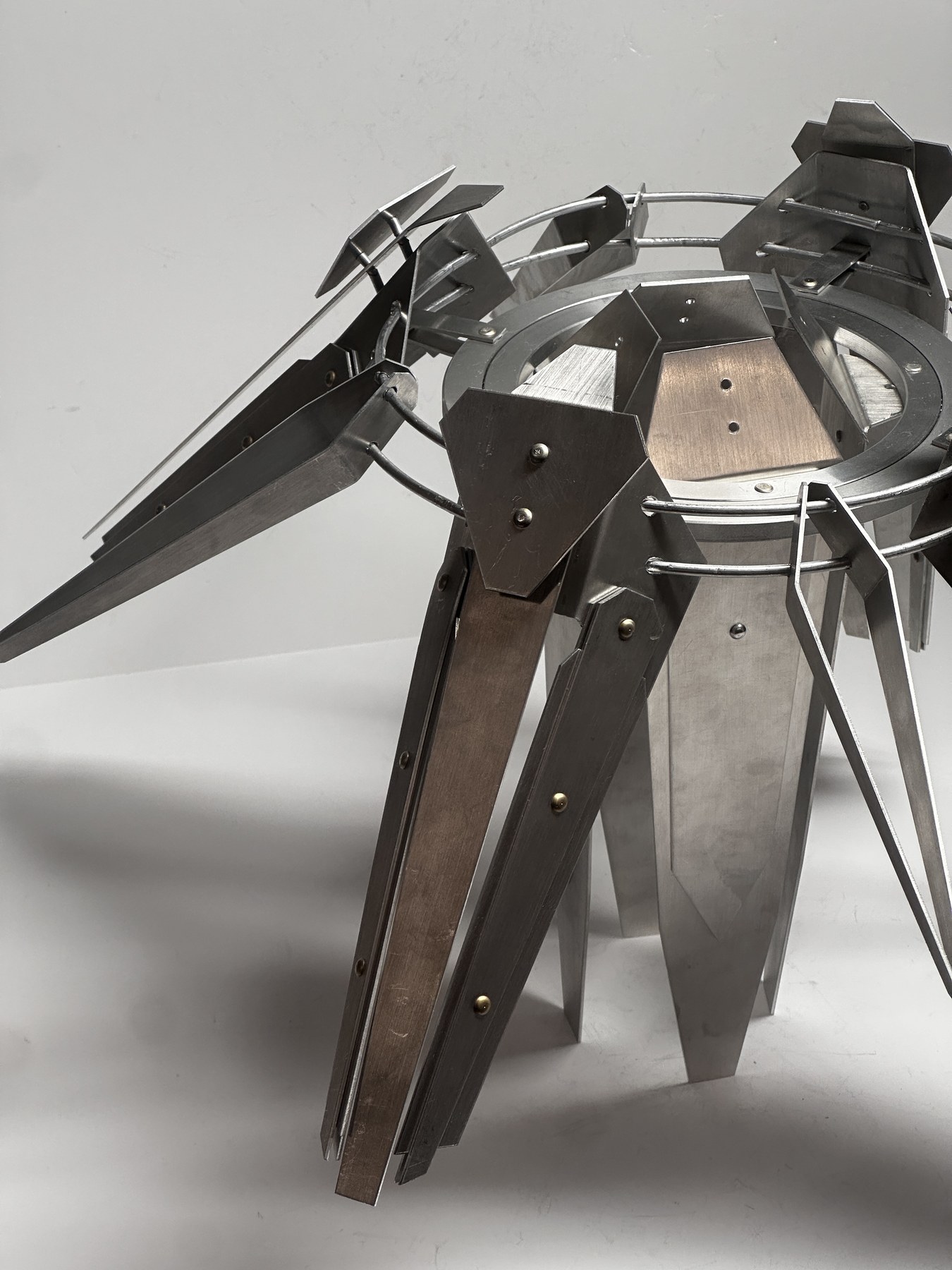
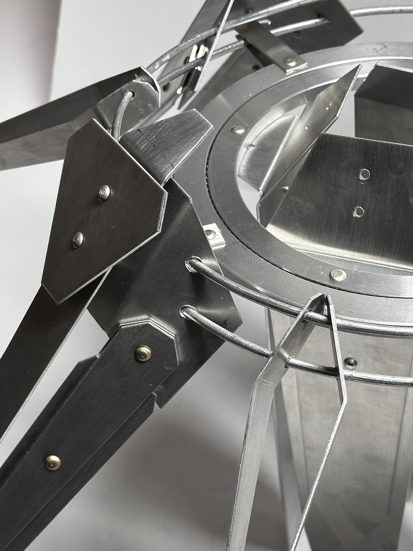
The front view clarifies the repeated geometry; the closer angle shows how long tapered plates, folded housings, and circular rails overlap without becoming one solid mass.
FIG 02 · FRONT ELEVATION
FIG 02 — REPEATED FINS · CENTRAL RING · RADIAL SILHOUETTE
Fasteners and offsets are treated as part of the visual language rather than hidden after assembly.
Folded plates locate the long fins around the ring, while bent rods maintain spacing between layers. The exposed junction makes the fabrication sequence readable and gives the object its mechanical character.
PRIMARYCUT ALUMINUM PLANES
SPACINGFORMED ROD RAILS
JOININGMECHANICAL FASTENERS
SEC 04
Volume in Hand体量与尺度
ONE OBJECT · THREE READINGS
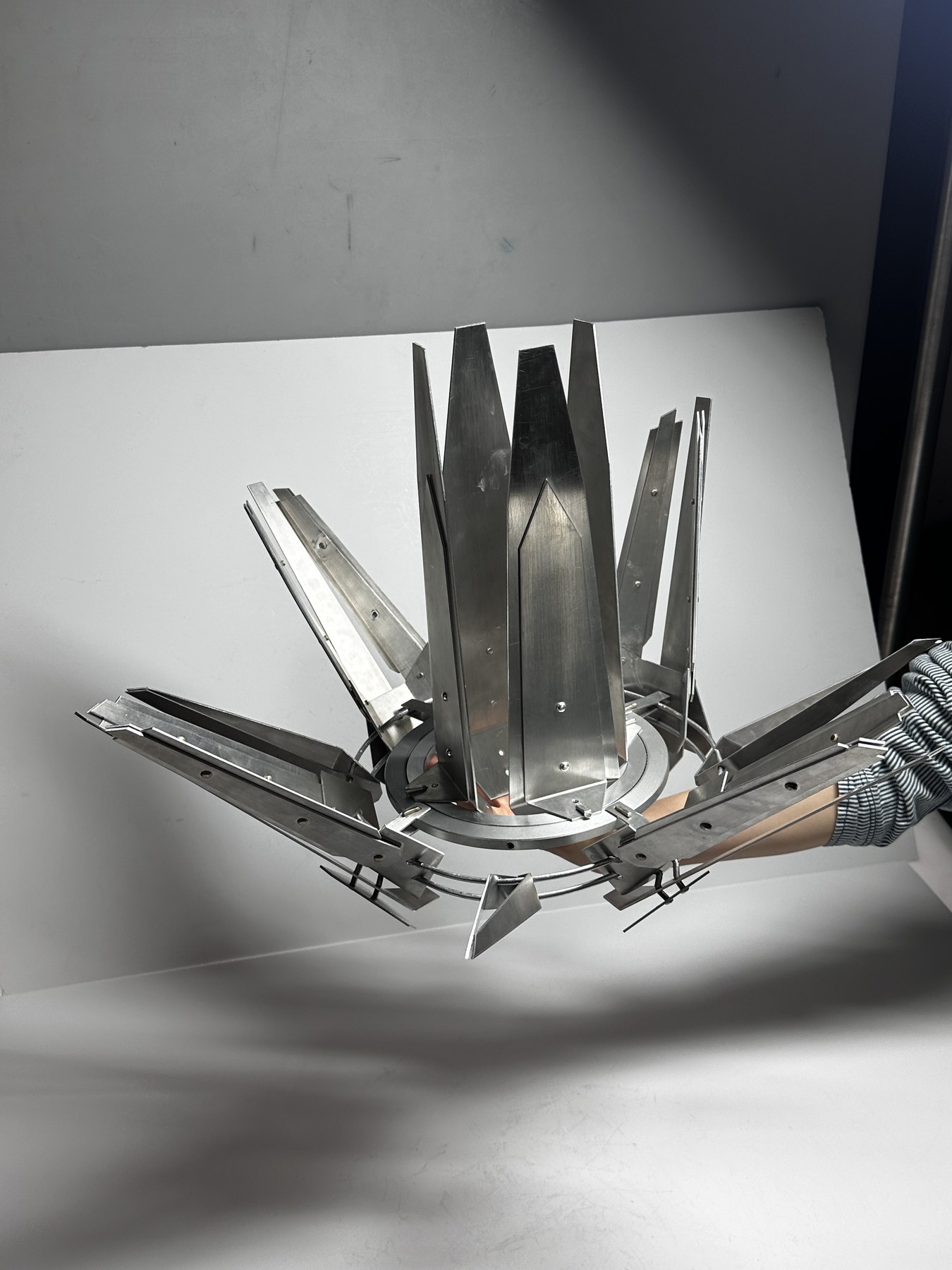
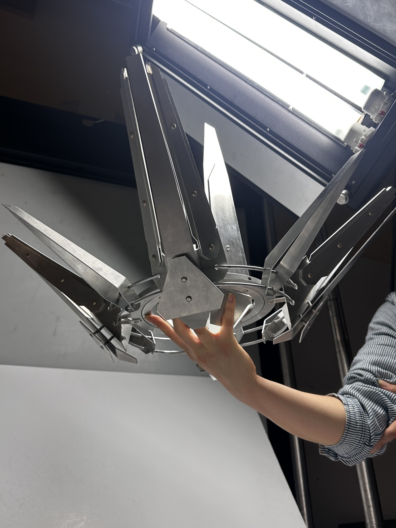
Hand scale and low viewpoints reveal the depth that the frontal silhouette conceals.
The finished prototype changes character by viewpoint: compressed and shield-like from above, open and radial underneath, and sharply directional from below.